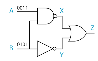
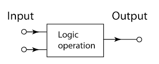
- A logic gate is a physical device that performs a logical operation on one or more logical inputs, and produces a only one logical output.
- The input is the signal or data that fed into a logic gate whereas the output is the result from processing the inputs by using the operation of the logic gate.
- The input and output can be either high (denoted by 1) or low (denoted by 0).
- Gates are identified by their function. The 5 basic logic gates that you need to know under SPM syllabus are
- the AND gate
- the OR gate
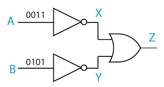
- the NOT gate
- the NAND gate
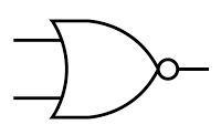
- the NOR gate
- Logic gates primarary work using diodes and transistors as switches.
Symbol of the Logic Gate
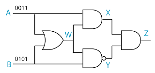
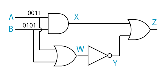
For each gate below, the input or inputs are on the left of the symbol. The output is on the right
The Truth Tables
- The function of a logic gates can be shown by using the Truth tables.
- A truth table lists all possible input together with the corresponding output.
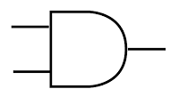
AND gate
Symbol:
Boolean Expression:
Truth Table:
| Truth Table |
| INPUT |
OUTPUT |
| 0 |
0 |
0 |
| 0 |
1 |
0 |
| 1 |
0 |
0 |
| 1 |
1 |
1 |
Notes:
The output is HIGH (1) only if both the inputs are HIGH (1).
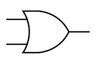
OR gate
Symbol:
Boolean Expression:
Truth Table:
| Truth Table |
| INPUT |
OUTPUT |
| 0 |
0 |
0 |
| 0 |
1 |
1 |
| 1 |
0 |
1 |
| 1 |
1 |
1 |
Notes:
The output is HIGH (1) only if one or more inputs are HIGH (1).
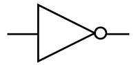
NOT gate
Symbol:
Boolean Expression:
Truth Table:
| Truth Table |
| INPUT |
OUTPUT |
| 0 |
1 |
| 1 |
0 |
Notes:
The output is the opposite of the input.
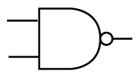
NAND gate
Symbol:
Boolean Expression:
Truth Table:
| Truth Table |
| INPUT |
OUTPUT |
| 0 |
0 |
1 |
| 0 |
1 |
1 |
| 1 |
0 |
1 |
| 1 |
1 |
0 |
Notes:
The output is LOW (0) only if both the inputs are HIGH (1).
NOR gate
Symbol:
Boolean Expression:
Truth Table:
| Truth Table |
| INPUT |
OUTPUT |
| 0 |
0 |
1 |
| 0 |
1 |
0 |
| 1 |
0 |
0 |
| 1 |
1 |
0 |
Notes:
The output is HIGH (1) only if both the inputs are LOW (0).