9.1.3 Cathode Ray Oscilloscope

(Cathode Ray Tube Television)
  1. Cathode-ray tubes have become part of everyday life.
  2. They can be found in the screens of television sets and computer monitors.
  3. In the Physics laboratory, we use the cathode-ray tube in the oscilloscope to study waveforms.
  4. In SPM, you need to know
    1. How cathode ray is produced (Thermionic emission and electron gun)
    2. The characteristics of cathode ray (Study by using the Maltese Cross Tube and Deflection Tube).
    3. the structure of a Cathode Ray Oscilloscope
    4. how to operate a Cathode Ray Oscilloscope
    5. the uses of a Cathode Ray Oscilloscope

(Cathode Ray Oscilloscope)


9.1.2 Cathode Ray

Electron Gun

(The electrons released by the cathode are accelerated by the accelerating anode and form a beam of electrons)
  1. If a high positive potential (anode) is placed in front of the heated metal, the emitted electrons will be accelerated and form a beam of electrons.
  2. The device is called an electron gun.
  3. The beam produced is called the cathode ray.

Properties of the cathode ray

The properties of cathode ray can be studied by using the Maltese Cross tube and the Deflection Tube.

Maltese Cross Tube

  1. We can use a Maltese cross tube to investigate the characteristics of cathode ray.
  2. Figure below shows the illustration of a Maltese Cross tube.

Experiment

6V DC Supply: ON

3kV EHT: OFF
The filament glows and emits light.
The light is blocked by the cross and hence a shadow is formed on the screen.

6V DC Supply: ON

3kV EHT: ON
The electrons are accelerated by the anode and hence produces a cathode ray.
The cathode ray hit on the screen cause a fluorescent effect.
The cathode ray is also blcok by the cross. Therefore, a shadow form on the screen.

6V DC Supply: ON

3kV EHT: OFF

with Magnet
The cathode ray can be deflected by the magnetic field.
The direction of deflection can be determined by Fleming's Left Hand Rule. (Note: The direction of current is in the opposite direction of electrons movement).

6V DC Supply: ON

3kV EHT: OFF

with Electric Plate
The cathode can be deflected by an electric field.

Deflection Tube


The characteristics of cathode ray can also be determined by using a refflection tube.

Conclusion

  1. Both the experiment of Maltese Cross Tube and the Deflection Tube show that
    1. Cathode ray can produce fluorescent effect.
    2. Cathode ray can be deflected by the electric field.
    3. Cathode ray can be deflected by the magnetic field. The direction of deflection can be determined by using Fleming’s Left hand Rule.


9.1.1 Thermionic Emission

  1. Thermionic emission is a process of emission of charge particle (known as thermion) from the surface of a heated metal.
  2. The charge particles normally are electrons.
  3. The rate of emission (number of electrons emitted in 1 second) is affected by 4 factors, namely
    1. the temperature of the heated metal,
      When the temperature of the metal increase, the emission rate of electron will increase.
    2. the surface area of the heated metal,
      When the surface area of the metal increase, the emission rate of electron will increase.
    3. the types of metal
      The rates of thermionic emission are different with regard to different types of metals.
    4. the coated material on the surface of the metal.
      If the surface is coated by a layer of barium oxide or strontium oxide, the rate of emission will become higher.

Thermionic Diode

  1. Thermionic emission is applied in thermionic diode.
  2. A diode is an electrical component that only allowed current flows in one direction.
  3. Figure below shows the illustration of a thermionic diode.
  4. Electrons can only released from the tungsten filament (when it is hot) and move toward the anode which is connected to the positive terminal.
  5. Electrons are not allowed to move in the opposite direction because no electrons will be released from the anode.
  6. As such, the electrons can only move from left to right but not the other way round.


8.5.3 Renewable and Non-renewable Energy

The frequently asked questions related to this topic are: what is renewable energy? the examples of Renewable and non-renewable energy and the advantages of using renewable energy.

Renewable energy sources are the energy sources which can be continuously replaced. Examples of renewable energy are:

  1. Hydro energy
  2. Solar energy
  3. Wind energy
  4. Geothermal energy
  5. Biomass
  6. Tidal energy


Advantages of Using Renewable Energy
1. Clean and do not pollute the environment.
2. Easily obtain.
3. Can be replenished once it has been used.
4. Can prevent energy crisis.

Hydroelectric


Advantages

  1. It is a renewable energy.
  2. Building a dam does not pollute the environment.
  3. In a lot of country, water can be easily obtained and is free.
  4. Building a hydroelectric plant does not involve very high technology as nuclear power plant.

Disadvantages

  1. Building a dam will cause a large area flooded with water, and hence seriously destroys the ecosystem nearby.
  2. The flooded area causes the loss of wild life habitat and agriculture land.
  3. Dam failure happens will cause a disaster to the lower reaches area of the river.
  4. The cost to build a dam is very high.

Fossil Fuel.

Advantages

  1. It is relatively easy to be collected as they are present in large amount in one place.
  2. It contains high energy capacity.

Disadvantages

  1. It releases a lot carbon dioxide when it is burned. Large amount of carbon dioxide presence in the atmosphere will cause the increase of the temperature of the atmosphere, known as global warming. Global warming is the most serious environmental problem that we are facing now.
  2. Fossil fuels are non-renewable energy.
  3. Pollute the air. Burning of fossil fuel will release particles and some hazardous gases such as sulphur dioxide and nitrogen dioxide which will pollute the air.

Solar Power

Advantages

  1. It is a renewable energy.
  2. Sunlight is free and can be obtained easily.
  3. It does not pollute the air.

Disadvantages

  1. A large area is needed to install the solar plate.
  2. The amount of sunlight at non-tropical area depends on the season.
  3. The energy collected need to be store in a cell so that it can be used at the time sunlight is not present.
  4. Its capacity is limited by the capacity of the cell. Normally a cell has relatively low capacity.

Nuclear Power

Advantages:

  1. The nuclear fuel such as uranium and plutonium has high energy capacity. Small amount of uranium can produces huge amount of energy.
  2. Nuclear energy does not pollute the air.

Disadvantages

  1. Hazardous radioactive waste is produced during nuclear reaction.
  2. The radioactive waste will cause pollution in a very large area if leakage happens in the nuclear power plan.
  3. The cost to maintain a nuclear plant is very high.
  4. Building a nuclear plant involving very high technology. Only a few countries own such technology.

Biomass

  1. Biomass is biological material derived from living organisms such as wood and animal waste.
  2. As a renewable energy source, biomass can either be used directly via combustion to produce heat, or indirectly after converting it to various forms of biofuel.
  3. Heat energy produced from the burning of biomass can be used to generate electricity.

Advantages

  1. It is renewable energy.
  2. Using biomass to generate electricity can reduce the disposal of organic waste.
  3. Liquid biofuels will not pollute the air because they are lead-free and sulphur-free.

Disadvantages

  1. Large storage space is required to store the biomass.
  2. Land utilization can be considerable. Can lead to deforestation.
  3. Overall process can be expensive

Wind Power


[This image is shared by Wagner Christian. This file is licensed under the Creative Commons Attribution ShareAlike 2.5 License. ]

Advantages

  1. It is a renewable energy.
  2. It does not pollute the environment.
  3. It is suitable for mountain area because the wind speed in mountain area is relatively high.

Disadvantages

  1. A large area is needed to build the windmills.
  2. The windmills will produce high level of noise.
  3. The power generated is inconsistent due to the inconsistent of the wind speed and wind direction.


8.5.2 What is a national Grid Network?


A national Grid Network is a network of cable that connects all the power stations in a country to transmit electricity to the consumers throughout the nation.

The advantages of the National Grid Network

  1. Reduces power lost during transmission. The potential difference is increased before transmission. This can reduce the current and hence reduces the energy lost during transmission.
  2. Electricity supply is more stable and reliable. This ensures a continuous supply of electrical energy to the whole country.
  3. Electric current can be distributed to different users according to the voltage requirement. Transformer is used to step down the voltage to certain level according to the needs of the consumers.
  4. Maintenance and repair work can be done at anytime. This is because any power stations can be shut down without affecting users in other areas.


8.5.1 Generation and Transmission of Electricity

Q: Why the voltage is stepped up before transmitting electricity over long distance?

A: Stepping up the voltage can reduces the current in the cable. This reduces the power loss in the cable during transmission.


[This image is shared by its author Aatu Liimatta in Wikipedia Image. This file is licensed under the Creative Commons Attribution ShareAlike 2.5 License.]

Problems Involving Electricity Transmission.

  1. Power Loss During Transmission. 
  2. The high voltage transmission cable is very dangerous. 
  3. The cost of the cables are high. 
  4. Charge leakage may happen between cables and earth. 
  5. Pylons may be struck by lightning. 
  6. Pylons and cables may be struck by light aircraft.


8.4.4 Factors That Affect the Efficiency

1. The heating effect of current in a coil.

Power is lost as heat I2R whereby I is the current flowing through the coil and R is the resistance of the coil

Methods to increase the efficiency
Use thick copper wires of low resistance. Use coolant to decrease the temperature of the transformer.

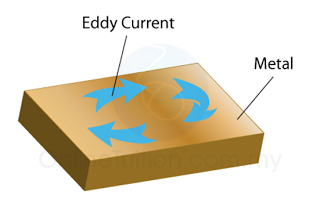
2. Heating effect of induced eddy currents


In the iron core. When the magnetic field in the iron core fluctuates, eddy currents are generated in the iron core.

Methods to increase the efficiency
Use a laminated iron core whereby each layer is insulated with enamel paint to prevent the flow of eddy currents. The high resistance between layers of the iron core decrease the prevalence of eddy currents and heat.

3. Magnetization of the Iron Core.

The energy used in the magnetization and de-magnetization of the iron core each time current changes its direction is known as hysterisis. This energy is lost as heat which subsequently heats up the iron core.

Methods to increase the efficiency
Use a soft iron core that is easily magnetized and de-magnetized.
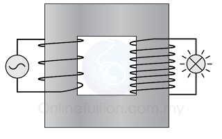
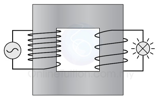
4. Flux leakage.

Some of the induced magnetic flux from the primary coil is not transmitted to the secondary coil, therefore the e.m.f in the secondary coil is decreased.
The secondary coil(windings) are intertwined tightly with the primary coils. The iron core should form a closed loop.

Methods to increase the efficiency
The secondary coil (windings) is intertwined tightly with the primary coils. The iron core should form a closed loop.


8.4.2 Types of Transformer

There are 2 types of transformer, namely

  1. the step up transformer
  2. the step down transformer

Step-up Transformer

  1. A step-up transformer is one where the e.m.f. in the secondary coil is greater than the e.m.f. in the primary coil. It is used to increases the potential difference.
  2. The number of windings in the secondary winding is greater than the number of windings in the primary coil.
  3. The current in the primary coil is greater than the current in the secondary coil.

Step-down Transformer

  1. Conversely, a step-down transformer is one where the e.m.f. in the secondary coil is less than the e.m.f. in the primary coil. It is used to reduce the potential difference.
  2. The number of windings in the primary winding is greater than the number of windings in the secondary coil. 
  3. The current in the primary coil is lesser than the current in the secondary coil.

Calculation of Potential Difference Change


Vp = input (primary) potential difference
Vs = output (secondary) potential difference
Ip = input (primary) current
Is = output (secondary) current