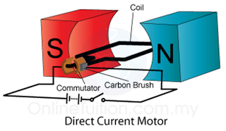
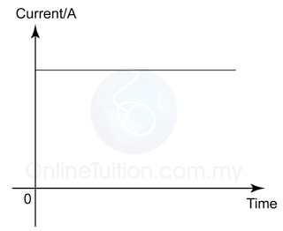
- Direct current is a uniform current flowing in one fixed direction in a circuit
- Direct current (d.c) is usually supplied by acid-based batteries or dry cells.
- A common example of acid-based (electrolyte) batteries is the car battery.
- Figure below shows the graph of current supplied by a dry cell over time.
Alternating Current
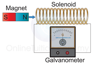
- Alternating current is an electric current in which the direction of flow of the electrons reverses periodically
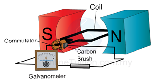
- Alternating current (a.c) is generated from alternating current generators such as hydroelectric power generators.
- The electricity supplied to households is alternating current.
- Household electricity (alternating current) changes direction 50 times every second. Its magnitude also changes with time.
Period And Frequency
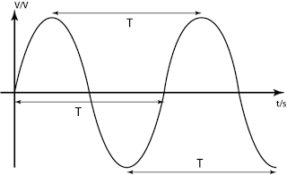
- The time taken for one complete cycle is known as the period, T.
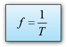
- The frequency f is defined as the number of complete cycles in 1 second.
- The relationship between the frequency and the period is:
- In SPM, you need to know the effect of both the direct current and alternating current on
- a bulb
- a capacitor
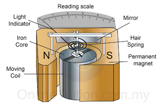
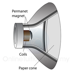
- a moving coil loudspeaker
- Table below give the summary of the comparison of the effect of direct current and alternating on a bulb, a capacitor and a moving coil loudspeaker.
| Direct Current | Alternating Current | |
| Effects on a bulb | The bulb lights up | The bulb lights up |
| Effects on a capacitor | Current is detected at the very beginning and then ceased to become zero afterward. | Current is detected |
| Effects on moving coil loudspeaker | No sound produced | Sound produced |
The Effective Voltage for a Sinusoidal Alternating Current
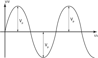
- The maximum potential difference supplied by an a.c source is known as the peak voltage VP.
- The effective potential difference for an a.c is equal to the potential difference of a alternating current if both results in the same heating effect.
- The effective potential difference for a.c is known as the root mean square voltage (r.m.s) of the a.c. and is given y the following equation:
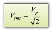
- The root-mean-square (r.m.s) value of an alternating current is the value of the steady direct current which produces the same power in a resistor as the mean power produced by the alternating current.
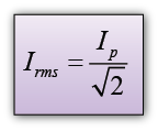
- The r.m.s current is the effective value of the alternating current.
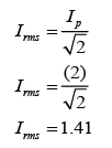
- The r.m.s. current can be calculated by using the following equation:
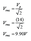
Example 1
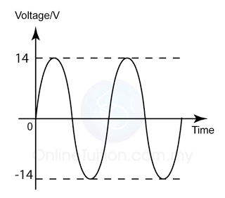
Diagram above shows a graph of potential difference, V against time, t of an alternating current. Find the Vr.m.s. of the power supply.
Answer:
Example 2
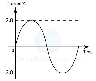
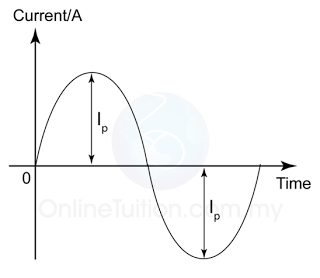
The diagram above shows the wave form of an a.c. supply. What is the root mean square value of the current?
Answer: