A solenoid is a long coil made up of a numbers of turns of wire.
Magnetic Field Pattern
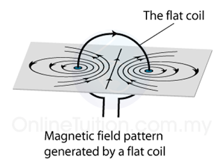
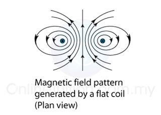
- Figure (a) illustrates the field pattern produced by a solenoid when current pass through it.
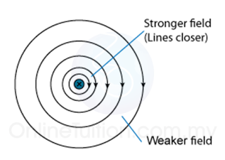
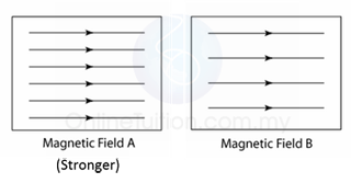
- The field lines in the solenoid are close to each other, indicates that the magnetic field is stronger inside the solenoid.
- We can also see that the field lines are parallel inside the solenoid. This shows that the strength of the magnetic filed is about uniform inside the solenoid.
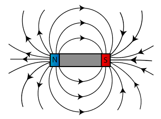
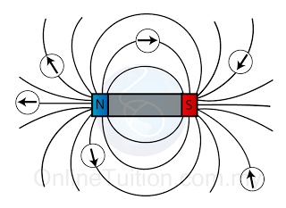
- We can also see that the magnetic field of a solenoid resembles that of the long bar magnet, and it behaves as if it has a North Pole at one end and a South Pole at the other.
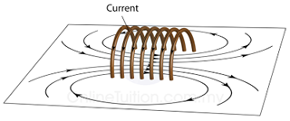 |
| (Figure (a): Magnetic field pattern of a solenoid) |
Determining the Pole of the Magnetic Field
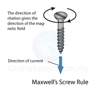
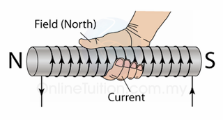
- The pole of the magnetic field of a solenoid can be determined by the Right Hand Grip Rule.
- Imagine your right-hand gripping the coil of the solenoid such that your fingers point the same way as the current. Your thumb then points in the direction of the field.
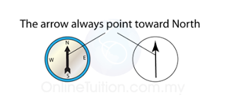
- Since the magnetic field lines always come out from the North Pole, hence the thumb points towards the North Pole.
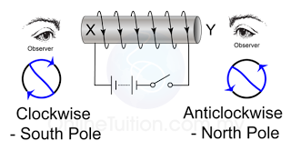
- There is another method can be used to determine the poles of the magnetic field forms by a solenoid.
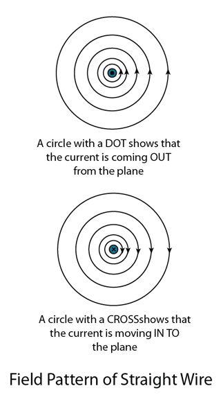
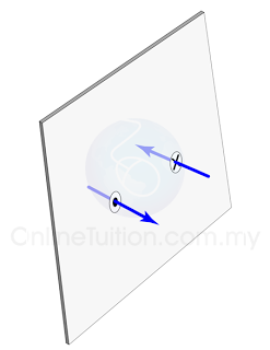
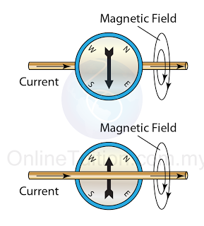
- Try to visualise that you are viewing the solenoid from the 2 ends as illustrated in figure (c) below.
- The end will be a North pole if the current is flowing in the aNticlockwise, or a South pole if the current is flowing in the clockwiSe direction.
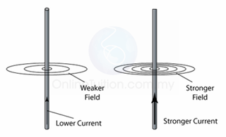
Strength of the Magnetic Field
The strength of the magnetic field can be increased by- increasing the current,
- increasing the number of turns per unit length of the solenoid,
- using a soft-iron core within the solenoid.