7.3.3 Current and Potential Difference

Series Circuit

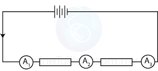
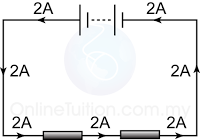
The current flow into a resistor = the current flow inside the resistor = the current flows out from the resistor

IA = IB = IC


In a series circuit, the current at any points of the circuit is the same.
Parallel Circuit
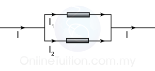
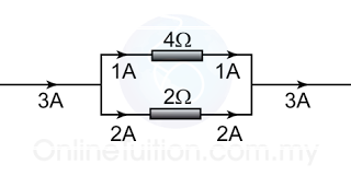
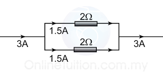
The current flow into a parallel circuit is equal to the sum of the current in each branches of the circuit.
I = I1 + I2
Example

If the resistance of the 2 resistors is the same, current will be divided equally to both of the resistor.

Series Circuit
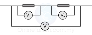

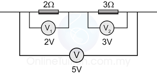
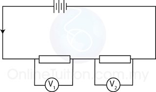
The sum of the potential difference across individual resistor in between 2 points in a series circuit is equal to the potential difference across the two points.

V = V1 + V2

Example

Parallel Circuit


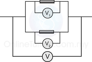
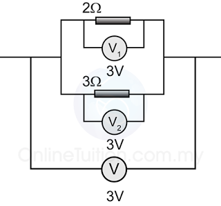
The potential difference across all resistors in a parallel circuit is the same.

V = V1 = V2

Example

Finding Current in a Series Circuit
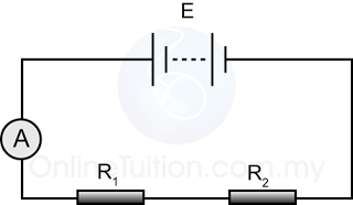
  1. In a series circuit, the current flow through each of the resistor is equal to the current flows through the whole circuit.
  2. Potential difference (V) across the whole circuit is equal to the e.m.f. (E) if the internal resistance is ignored.
  3. Effective resistance for the whole circuit = R1 + R2
  4. By Ohm’s Law


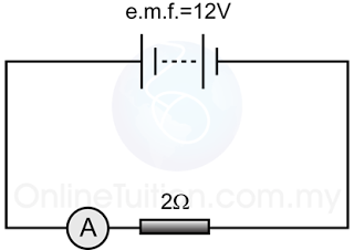
Example 1

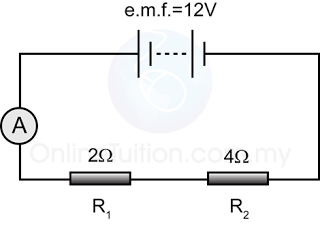
For the circuit in the diagram above,
  1. find the reading of the ammeter.
  2. find the current flows through the resistor.

Answer:
a.
Potential difference across the 2Ω resistor, V = 12V
Resistance, R =2Ω

V = IR
(12) = I(2)
I = 12/2 = 6A
b.
The current flows through the resistor
= the reading of the ammeter
= 6Ω
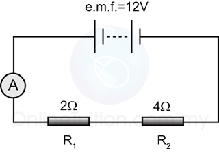

Example 2

For the circuit above,
  1. find the reading of the ammeter.
  2. find the current flows through each of the resistors.


Answer:
a.
Potential difference across the 2 resistors, V = 12V
The equivalent resistance of the 2 resistors, R =6Ω

V = IR
(12) = I(6)
I = 12/6 = 2A

b.
The current flows through the resistors
= the reading of the ammeter
= 2Ω

Finding Current in a Parallel Circuit
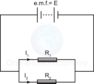

In parallel circuit, the potential difference (V) across each of the resistors is equal to the e.m.f. (E) if the internal resistance of the cell is ignored.

By Ohm’s Law
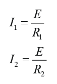


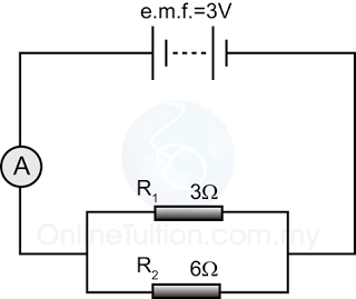
Example 1:


For the diagram above,
a. find the reading of the ammeter.
b. find the current in each of the resistors.

Answer:
a.
Effective resistance of the 2 resistors in parallel

Potential difference across the 2 resistance, V = 3V
V = IR
(3) = I(2)
I = 3/2 = 1.5A

Reading of the ammeter = 1.5A
b.
Current in the 3Ω resistor,
V = IR
(3) = I(3)
I = 3/3 = 1A

Current in the 6Ω resistor,
V = IR
(3) = I(6)
I = 3/6 = 0.5A

Example 2


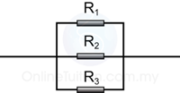
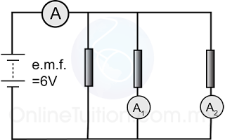
Figure above shows 3 identical resistors connected in parallel in a circuit. Given that the resistance of the resistors are 6Ω each. Find the reading of all the ammeters in the figure above.
Answer:
The potential diffrence across the resistors V = 6V
For ammeter A,
The equivalent resistance = 6/3 = 2Ω.
V = IR
(6) = I(2)
I = 6/2 = 3A

For ammeter A1,
V = IR
(6) = I(6)
I = 6/6 = 1A

For ammeter A2,

V = IR
(6) = I(6)
I = 6/6 = 1A

Finding Potential Difference in a Series Circuit
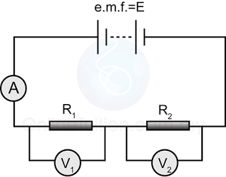

In the circuit above, if the current in the circuit is I, then the potential difference across each of the resistor is

Example


Find the potential difference across each of the resistors in the diagram above.

Answer:
The potential difference across the 2 resistors, V = 12V
The equivalent resistance of the 2 resistors, R = 2 + 4 = 6Ω
Current pass through the 2 resistor,


For resistor R1,
V = IR
V = (2)(2) = 4V

For resistor R2
V = IR
V = (2)(4) = 8V


7.3.2 Resistance in Series and Parallel Circuit

  1. In a series circuit, the effective resistance is equal to the sum of the individual resistance, as shown in the following equation. 

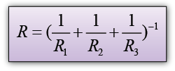
  2. In a parallel circuit, the effective resistance of the resistors can be calculated fro the following equation. 


Example:


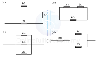
Find the equivalent resistance of the connection shown in the diagram above.

Answer:
(a)
R = 2 + 3 + 6 = 11Ω

(b)

(c)

(d)

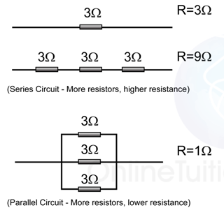
  1. In a series circuit, the more resistors with equal resistance in the circuit, the higher the effective resistance of the circuit.
  2. In a parallel circuit, the more resistors with equal resistance in the circuit, the lower the effective resistance of the circuit.

Finding the Resistance of an Individual Resistor

Example


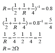
Given that the equivalent resistance of the connection in the figure above is 0.8Ω, find the resistance of the resistor R.

Answer:


Example


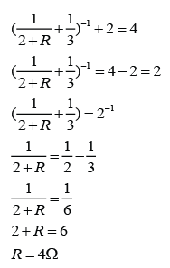
Given that the equivalent resistance of the connection in the figure above is 4Ω, find the resistance of the resistor R.

Answer:


7.2.4 Factors Affecting the Resistance in a Conductor


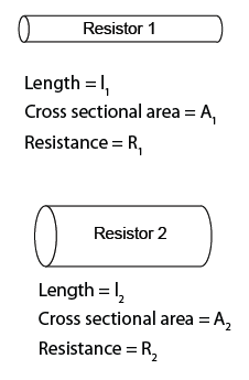
The resistance R of a given conductor depends on:
  1. its length l,
  2. its cross-sectional area A
  3. its temperature and
  4. the type of material.

Length


Resistance is directly proportional to the length of the conductor.

Cross Sectional Area


Resistance is inversely proportional to the cross sectional area of the conductor.

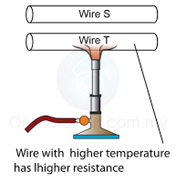
Temperature


A conductor with higher temperature has higher resistance.

Material

Difference materials have difference resistivity. The resistance of copper wire is lower than iron wire.

Since resistance is directly proportional to the length and inversely proportional to the cross sectional area of the conductor. If two resistors of same material have same temperature, we can relate the resistance of the two resistors by the following equation.


7.2.3 Resistance

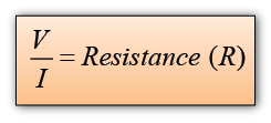
  1. The resistance R of a material is defined as the ratio V : I, where V is the potential difference across the material and I is the current flowing in it.
  2. The SI unit of resistance is the ohm (W). One ohm is the resistance of a material through which a current of one ampere flows when a potential difference of one volt is maintained.

Finding Resistance from the Potential Difference - Current Graph

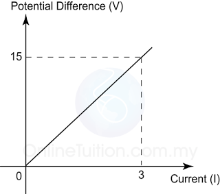
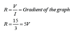
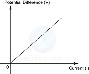
In the graph potential difference against current, the gradient of the graph is equal to the resistance of the resistor.

Resistance, R = Gradient of the Graph


Example:


Figure above shows the graph of potential difference across a wire against its current. Find the resistance of the wire.

Answer:
Resistance

Ohmic Conductor

  1. Conductors that obey Ohm’s law are said to be ohmic conductor.
  2. Examples of Ohmic conductor: Metal, Copper sulphate solution with copper electrodes

Non-Ohmic Conductor

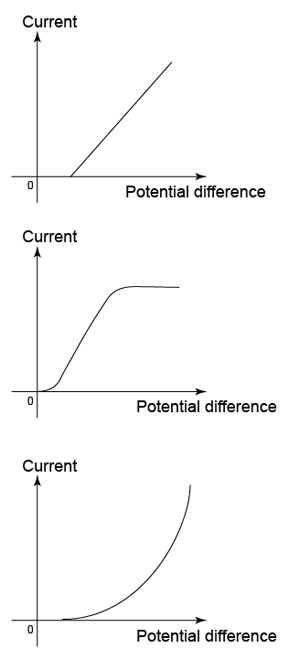
  1. Conductors which do not obey Ohm’s law are called non-ohmic conductor.
  2. Example: Semiconductor Diode, Vacuum tube diode

(Examples of characteristic of non-Ohmic conductor)


7.2.2 Relationship Between Current and Potential Difference

Ohm’s Law

  1. The relationship between the current passing through 2 points in a conductor and the potential difference between the 2 points is given by Ohm's law.
  2. Ohm’s Law states that the current flowing in the metallic conductor is directly proportional to the potential difference applied across it’s ends, provided that the physical conditions ( such as temperature ) are constant.

    where k is a constant

Example:
What is the current flow through an 800Ω toaster when it is operating on 240V?

Answer:
Resistance, R = 800Ω
Potential difference, V = 240V
Current, I = ?


7.2.1 Potential Difference

Potential and Potential Difference

  1. The electric potential V at a point in an electric field is the work done to bring a unit ( 1 Coulomb) positive charge from infinity to the point.
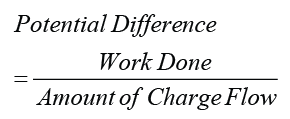
  2. The potential difference (p.d.) between two points is defined as the work done in moving 1 Coulomb of positive charge from 1 point in an electric field to another point.
  3. In mathematics

    or

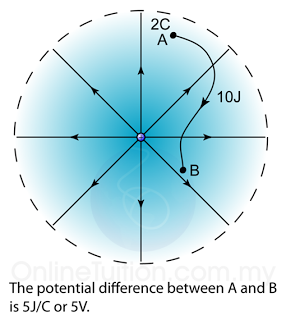
  1. Example, in the diagram above, if the work done to move a charge of 2C from point A to point  is 10J, the potential difference between A and B,

Example:
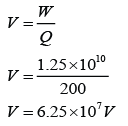
During an occasion of lightning, 200C of charge was transferred from the cloud to the surface of the earth and 1.25×10¹⁰J of energy was produced. Find the potential difference between the cloud and the surface of the earth.

Answer:
Work done, W = 1.25×10¹⁰J
Charge transferred, Q = 200C
Potential difference, V = ?

Arrangement of Ammeter


To use the ammeter in the measurement of an electric current, the ammeter must be connected in series to the circuit.

Arrangement of Voltmeter


To use the voltmeter in the measurement of potential difference across an object, the voltmeter must be connected in parallel to the circuit.


7.1.4 The Effect of Electric Field

Effect of Electric Field on a Ping Pong Ball Coated with Conducting Material

  1. A ping ball coated with conducting material is hung by a nylon thread.
  2. When the ping pong ball is placed in between 2 plates connected to a Extra High Tension (E.H.T.) power supply, opposite charges are induced on the surface of the ball. The ball will still remain stationary. This is because the force exert on the ball by the positive plate is equal to the force exerted on it by the negative plate.
  3. If the ping pong ball is displaced to the right to touch the positive plate, it will then be charged with positive charge. Since like charges repel, the ball will be pushed towards the negative plate.
  4. When the ping pong ball touches the negative plate, it will be charged with negative charge. Again, like charge repel, the ball will be pushed towards the positive plate. This process repeats again and again, causes the ping pong ball oscillates to and fro continuously between the two plates.

Candle Flame in an Electric Field

  1. Normally, with absent of wind, the flame of a candle is symmetry.
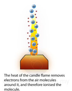
  2. The heat of the candle flame removes electrons from the air molecules around it, and therefore ionised the molecule. As a result, the flame is surrounded by a large number of positive and negative ions.
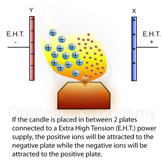
  3. If the candle is placed in between 2 plates connected to a Extra High Tension (E.H.T.) power supply, the positive ions will be attracted to the negative plate while the negative ions will be attracted to the positive plate.
  4. The spreading of the flame is not symmetry. This is because the positive ions are much bigger than the negative ions; it will collide with the other air molecule and bring more air molecule towards the negative plate.


7.1.3 Electric Field

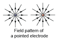
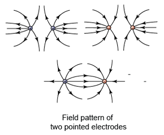
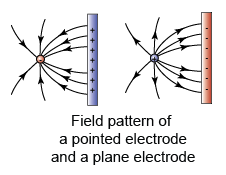
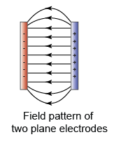
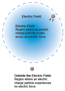
  1. An electric field is a region in which an electric charged particle experiences an electric force.
  2. Electric field is represented by a number of lines with arrows, called electric lines of force or electric field lines.
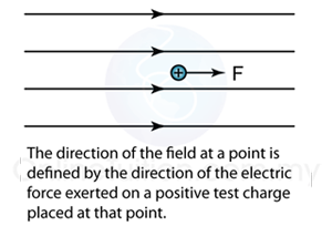
  3. The direction of the field at a point is defined by the direction of the electric force exerted on a positive test charge placed at that point.
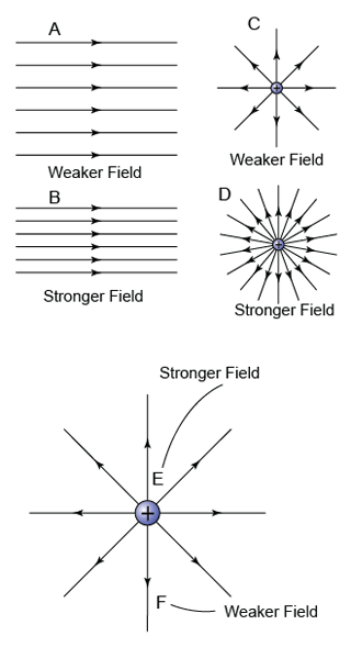
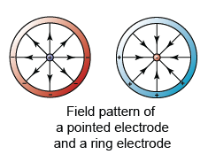
  4. The strength of the electric field is indicated by how close the field lines are to each other. The closer the field lines, the stronger the electric field in that region.
    Example
  5. The lines of force are directed outwards for a positive charge and inwards for a negative charge.
  6. The electric line of force will never cross each other.
  7. The figure shows a few examples of the field pattern that you need to know in the SPM syllabus.


7.1.2 Current

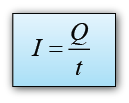
  1. An electric current I is a measure of the rate of flow of electric charge Q through a given cross-section of a conductor.
  2. In other words, current is the measure of how fast the charge flow through a cross section of a conductor.

Equation


or


Direction of Current

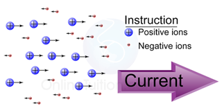
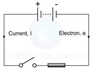
  1. Conventionally, the direction of the electric current is taken to be the flow of positive charge.
  2. The electron flow is in the opposite direction to that of the conventional current.
  3. In a circuit, current flow from the positive terminal to the negative terminal.
  4. In a circuit, electrons flow from the negative terminal to the positive terminal.

Unit of Current

  1. The SI unit for current is the ampere (A).
  2. The current at a point is 1 ampere if 1 Coulomb of electric charge flows through that point in 1 second. Therefore, 1 A = 1C/s.

Example 1:
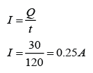
If 30 C of electric charge flows past a point in a wire in 2 minutes, what is the current in the wire?

Answer:
Charge flow, Q = 30C
Time taken, t = 2 minutes = 120s

Current,


Example 2:
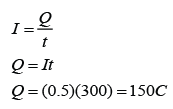
Current of 0.5A flowed through a bulb. How many electrons had flowed through the bulb in 5 minute? (The charge of 1 electron is equal to -1.6×10⁻¹⁹ C)

Answer:
Current, I = 0.5A
Time taken, t = 5 minutes = 300s

Charge of 1 electron, e = -1.6×10⁻¹⁹ C
Number of electrons, n = ?